
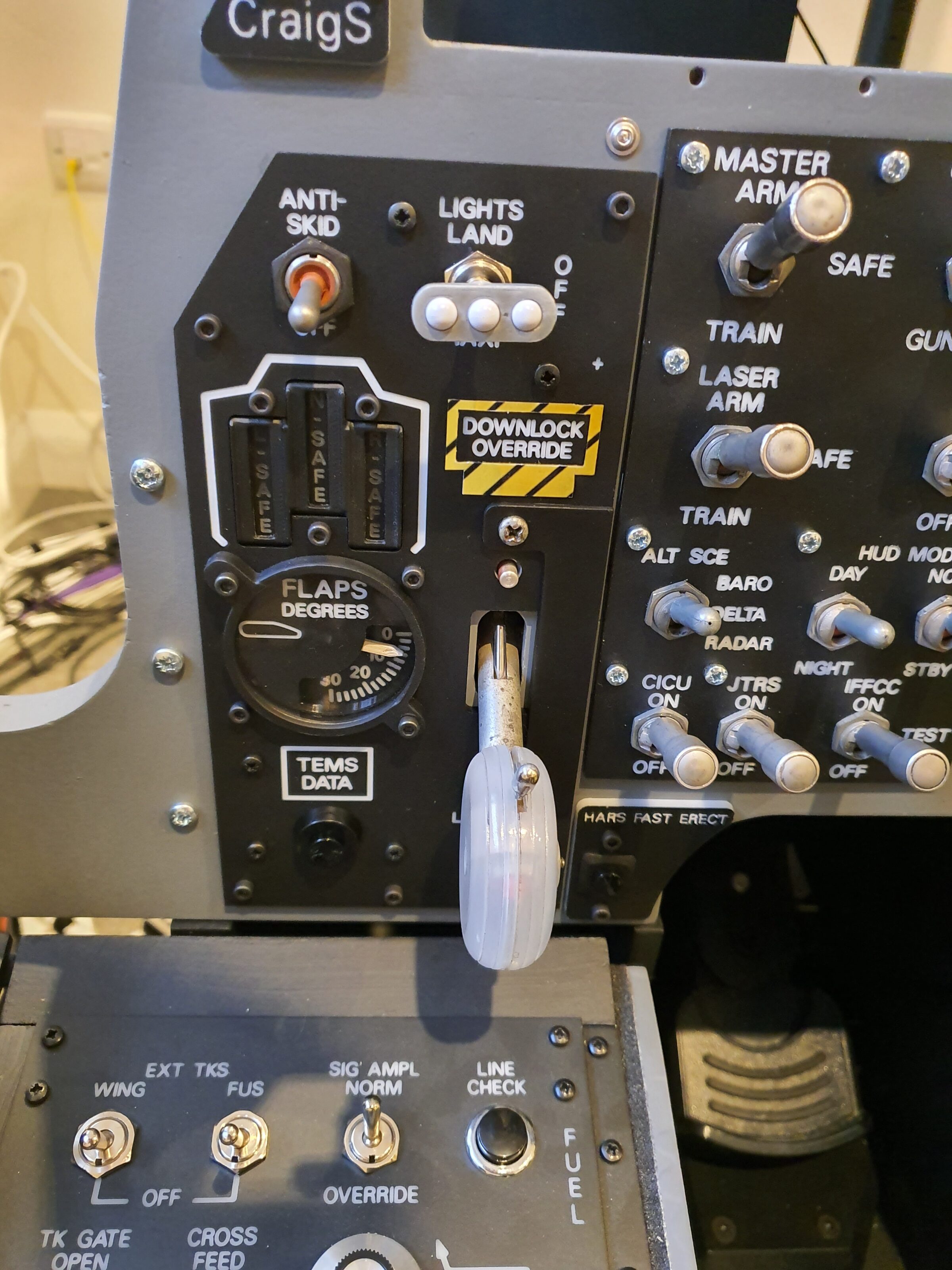
The Landing Gear Panel was great to build with lots of learnings because it was so varied in terms of the parts within it. It contained: a magnetically held toggle for Anti-skid, 3D designed and printed toggle cap for the Landing Lights, a series of LEDs suspended within a 3D printed enclosure with raised bezel for Landing Gear lights, a servo for Flaps position and a real Landing Gear Lever from a Tornado.
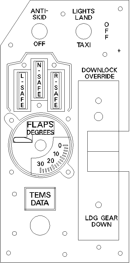
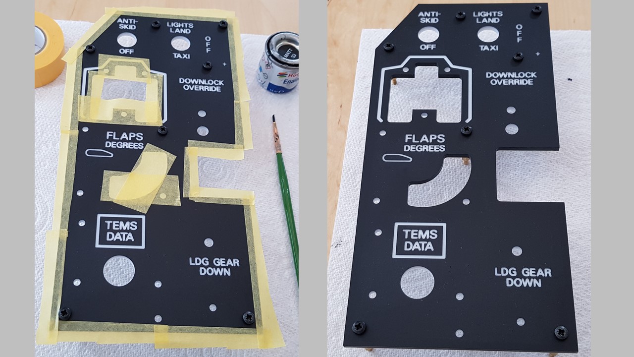
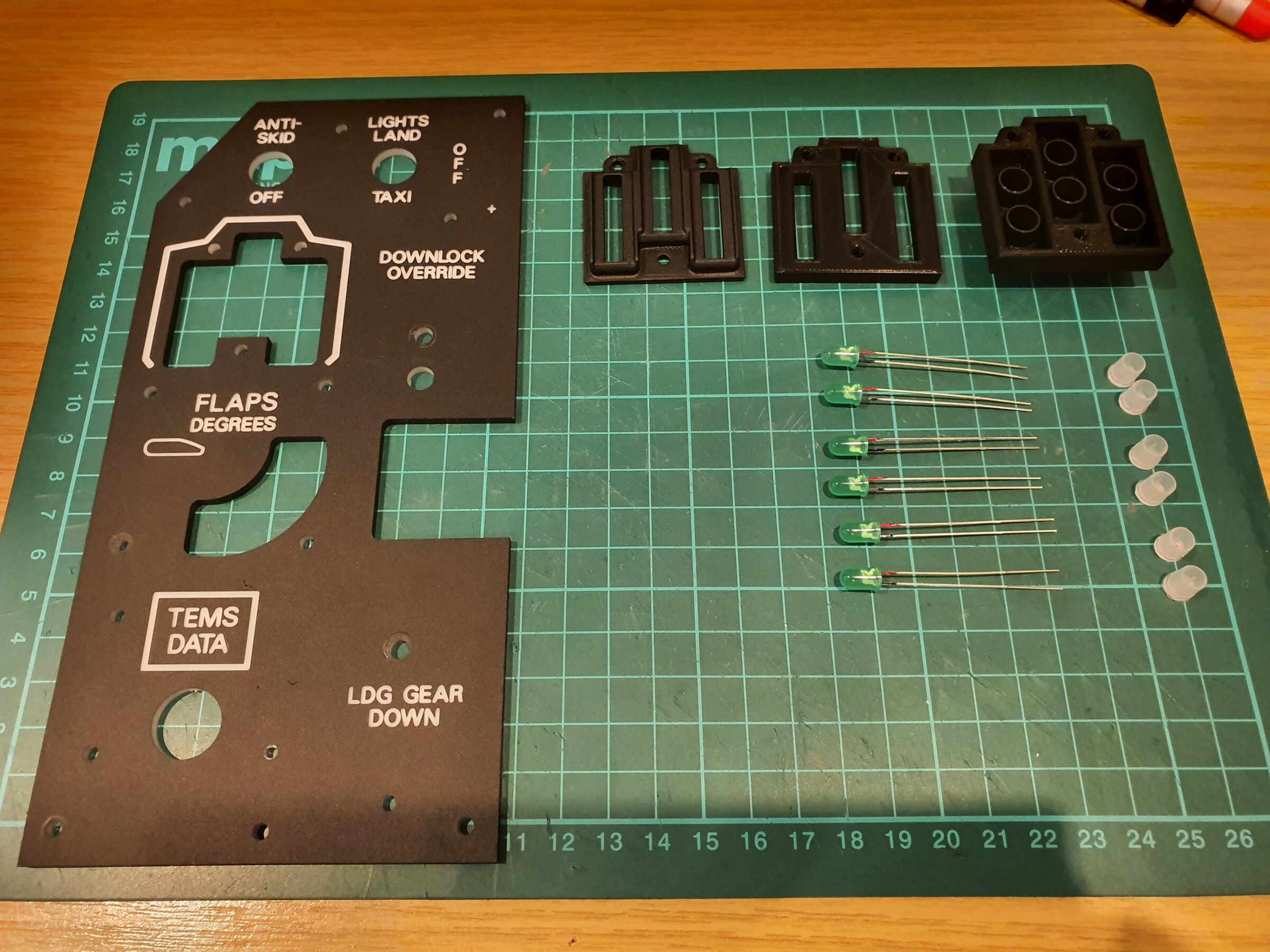
I took my CAD / CAM design and test fit components (See above). I then CNC machined the panel and painted all inner and outer edges (See below)
With the fascia produced (above), I turned my attention to each component that will be housed behind it.
I sourced two Landing Gear Levers from Tornados. One was damaged and I used that to take parts and incorporate into the other. For this item I wanted to use the original lamps (bulbs) if possible and between them had enough working bulbs.

I have to say that whilst using original aircraft parts can have its challenges – the feeling of actuation in using this Landing Gear Lever is truly immense.
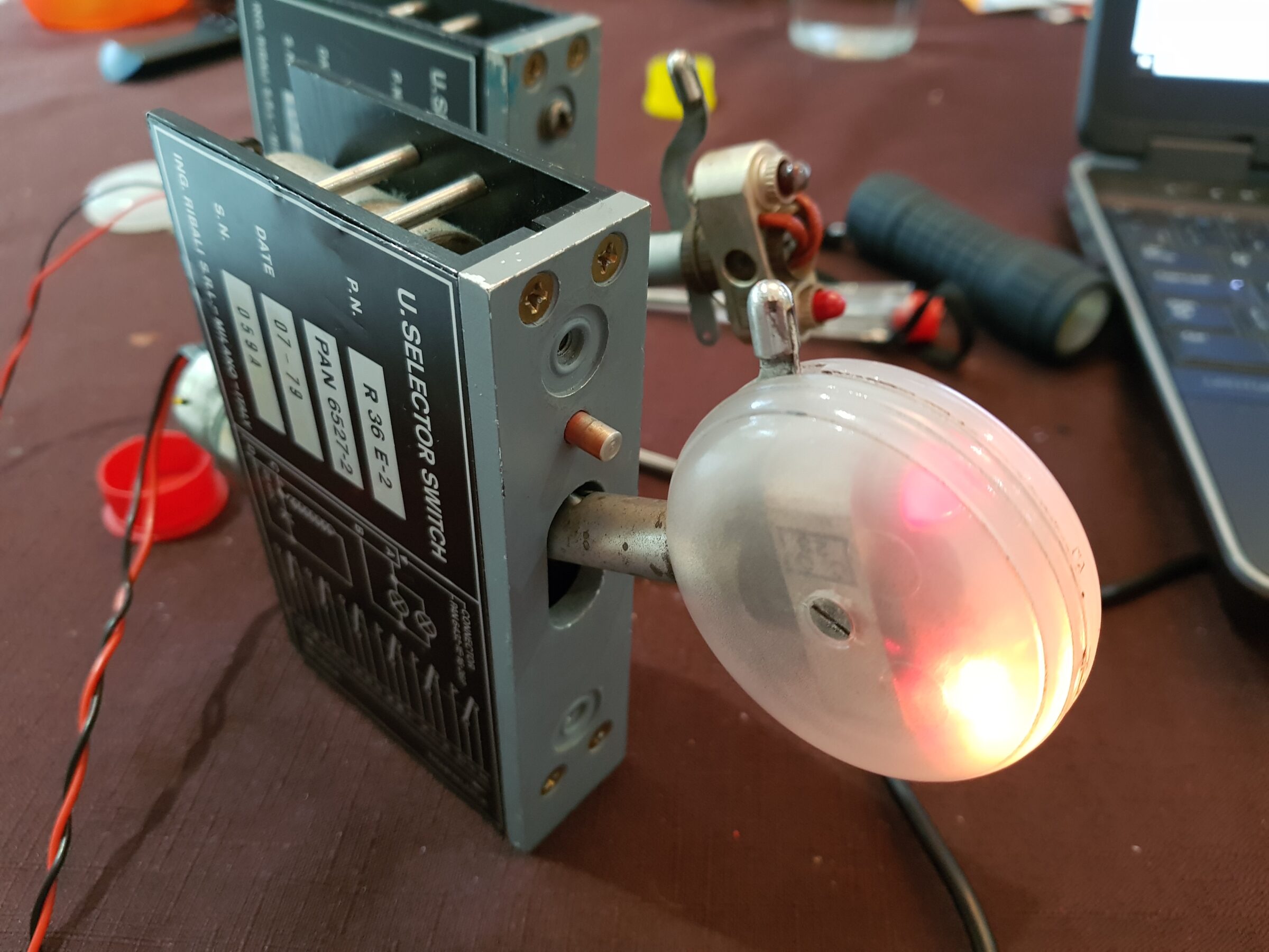
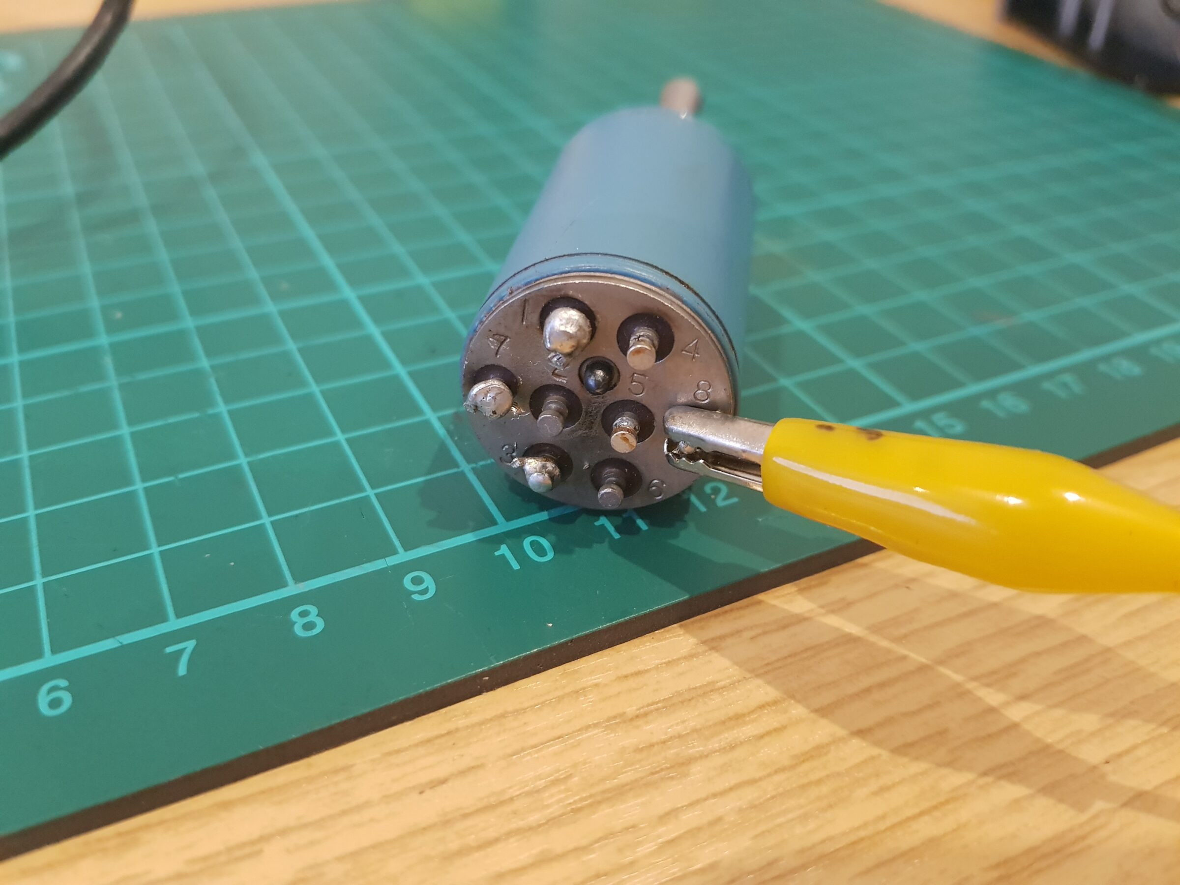
I spent time to map out and test all the connection pins on the magnetically held toggle (See below) for Anti-skid. I also ran a number of tests using various voltages to see which would work best – that being the holding force whilst in the (on) position.
I lay out a number of key parts ready for assembly (see below)
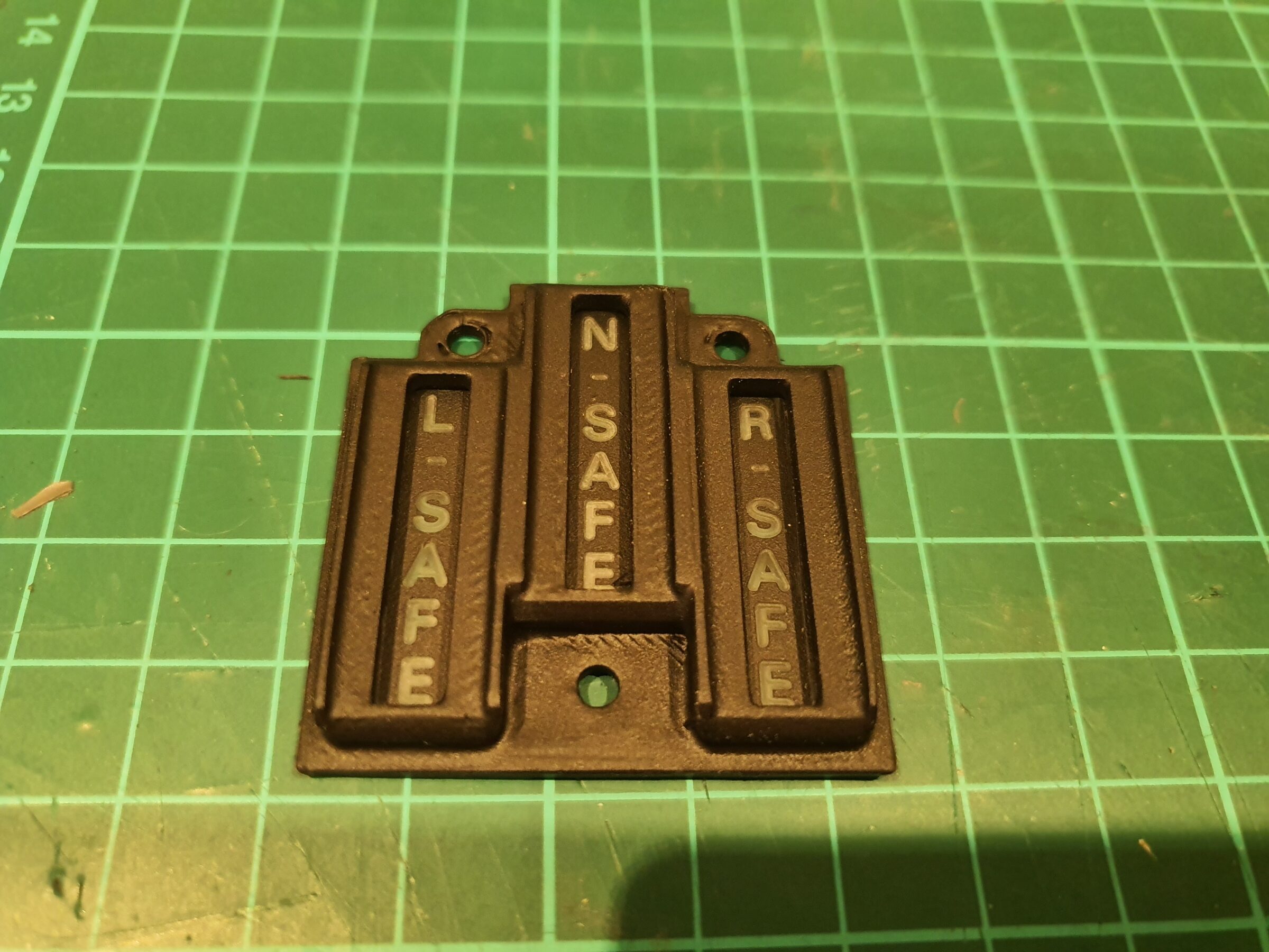
The Landing Gear Position Lights went through a number of revisions to arrive at the below.
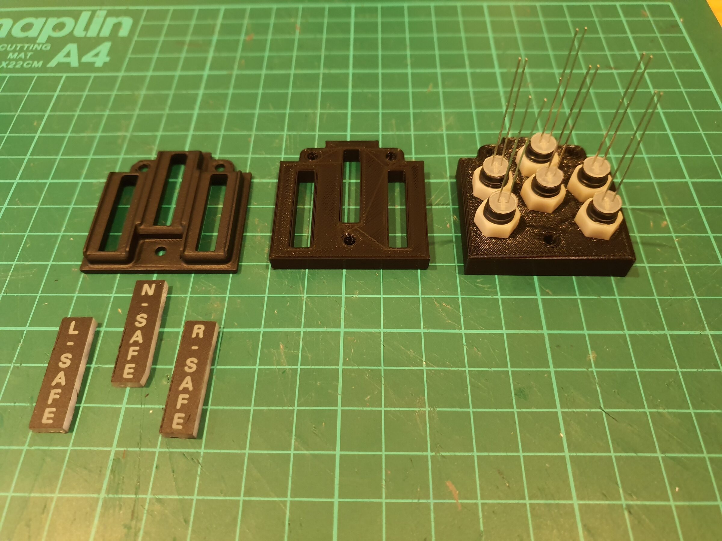
When compared to the Emergency Flight Control Panel (Trim Panel) I built for the Left Console, it was worth the extra time to create a holder with a bezel.
The below GIF shows one of a number of tests I undertook when incorporating the Landing Gear lights into the panel. You can see the lights activated within the sim (on laptop screen) and also on the physically build panel.
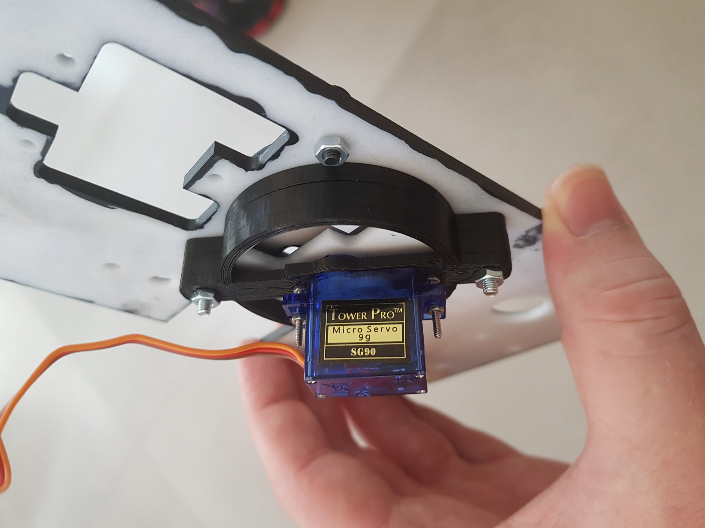
I designed and 3D printed a bracket to hold the servo (for Flap control) in position. It follows the footprint of the bezel on the fascia front but with a mounting plate through the centre. This therefore allows the transmission of light for backlighting.
We can see an image (below left) of a Landing Lights toggle. We can also see a 3D test print of the toggle caps I did to replicate it along with my final version to install (bottom right). I made several, so would have a number to choose from, and used two different paints (a military grey and a metallic silver) to see which would look best. The metallic silver worked for me.

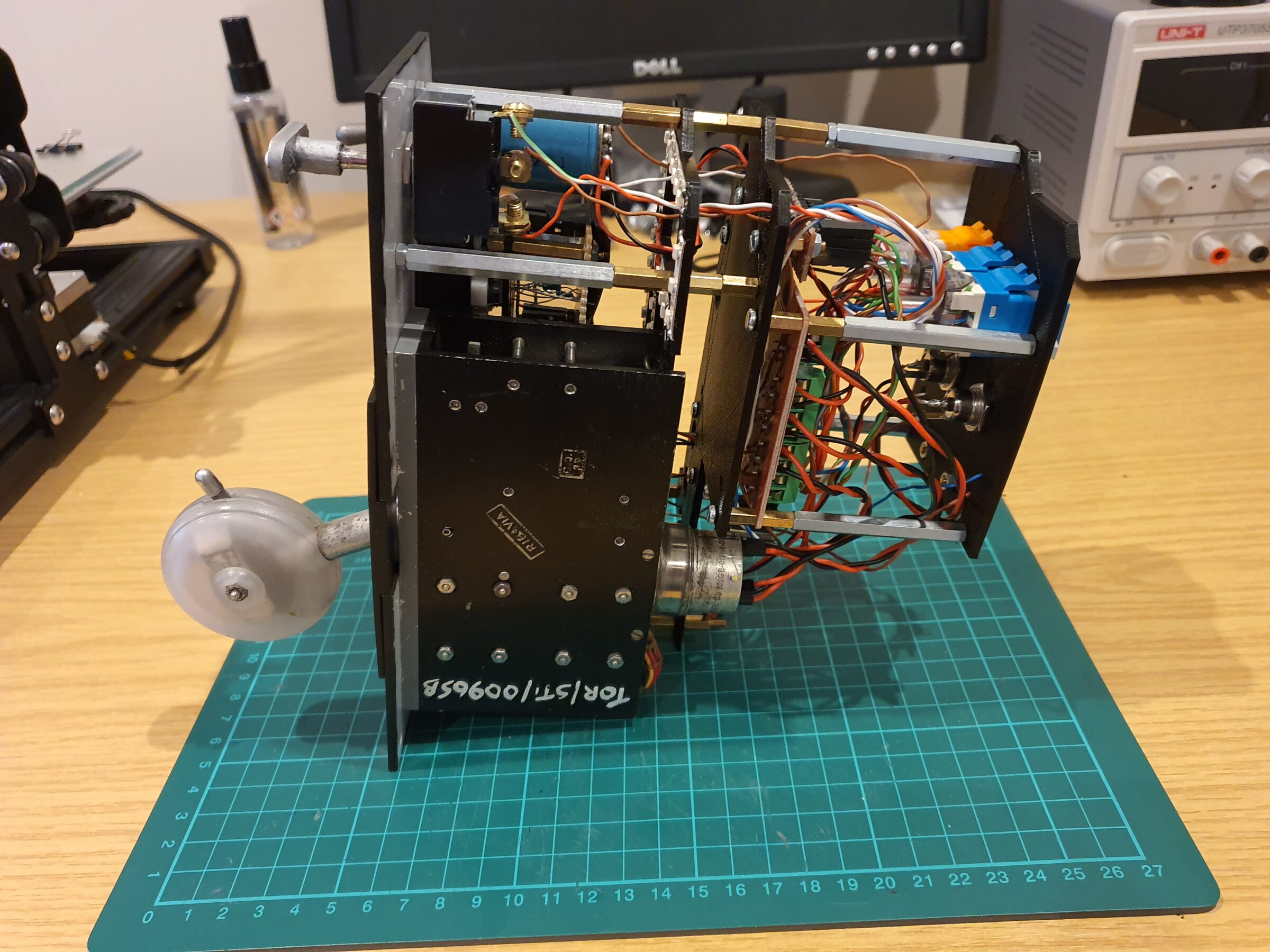
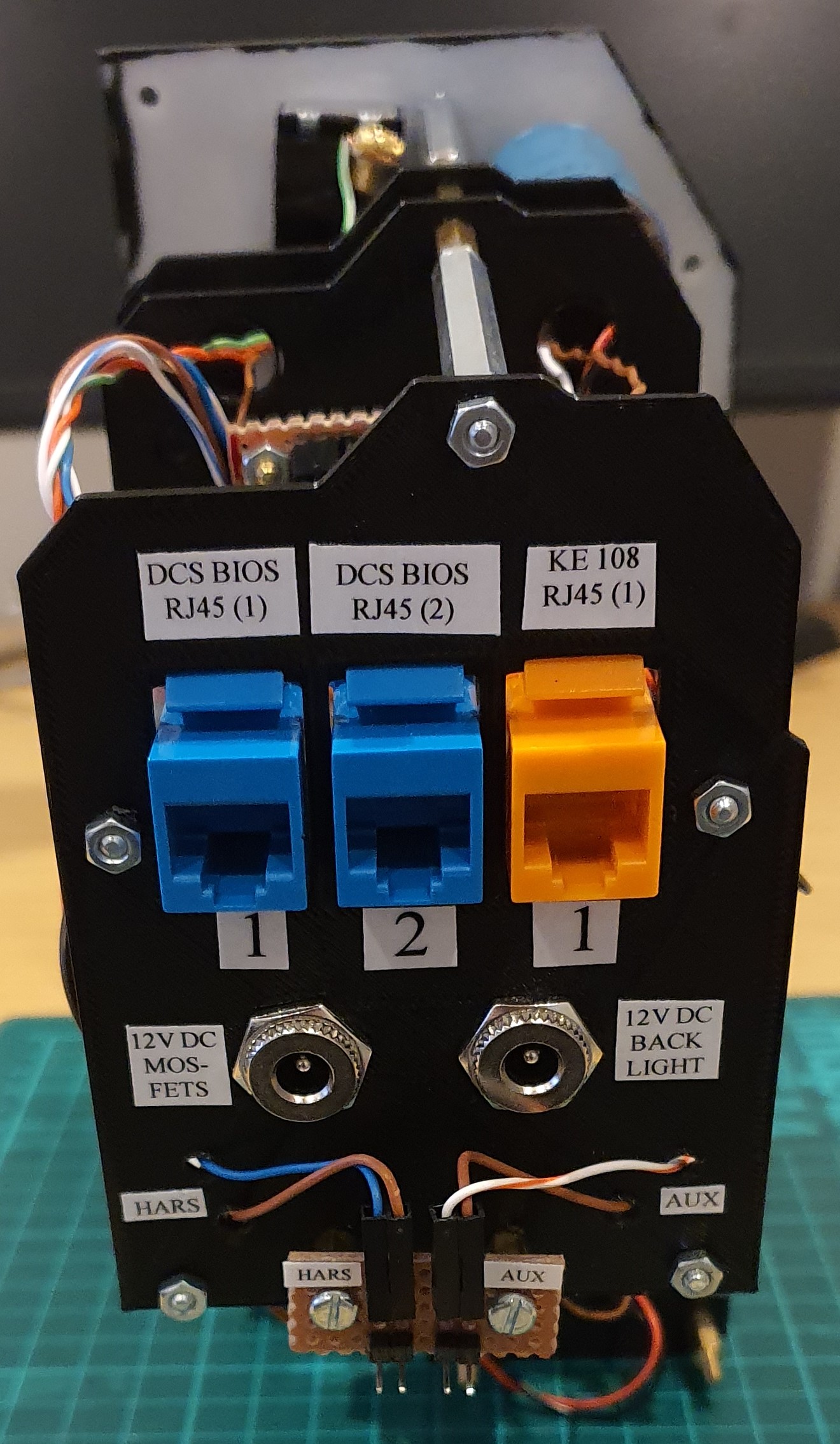
Below we can see the completed panel from a side and rear view – and then installed into the Front Dash frame.
For more detail around the design and construction of this panel – see the below YouTube Video – Front Dash Part 14: Landing Gear Panel