
ENGINE INSTRUMENT PANEL
This was the first panel built for the front dash as a prototype.
The A10C cockpit has a large number of gauges and therefore I wanted to understand how these can be implemented into my simpit. The engine instrument cluster is a good choice to build if wanting to learn this, as it contains the greatest number of gauges within any one single panel within the A10.
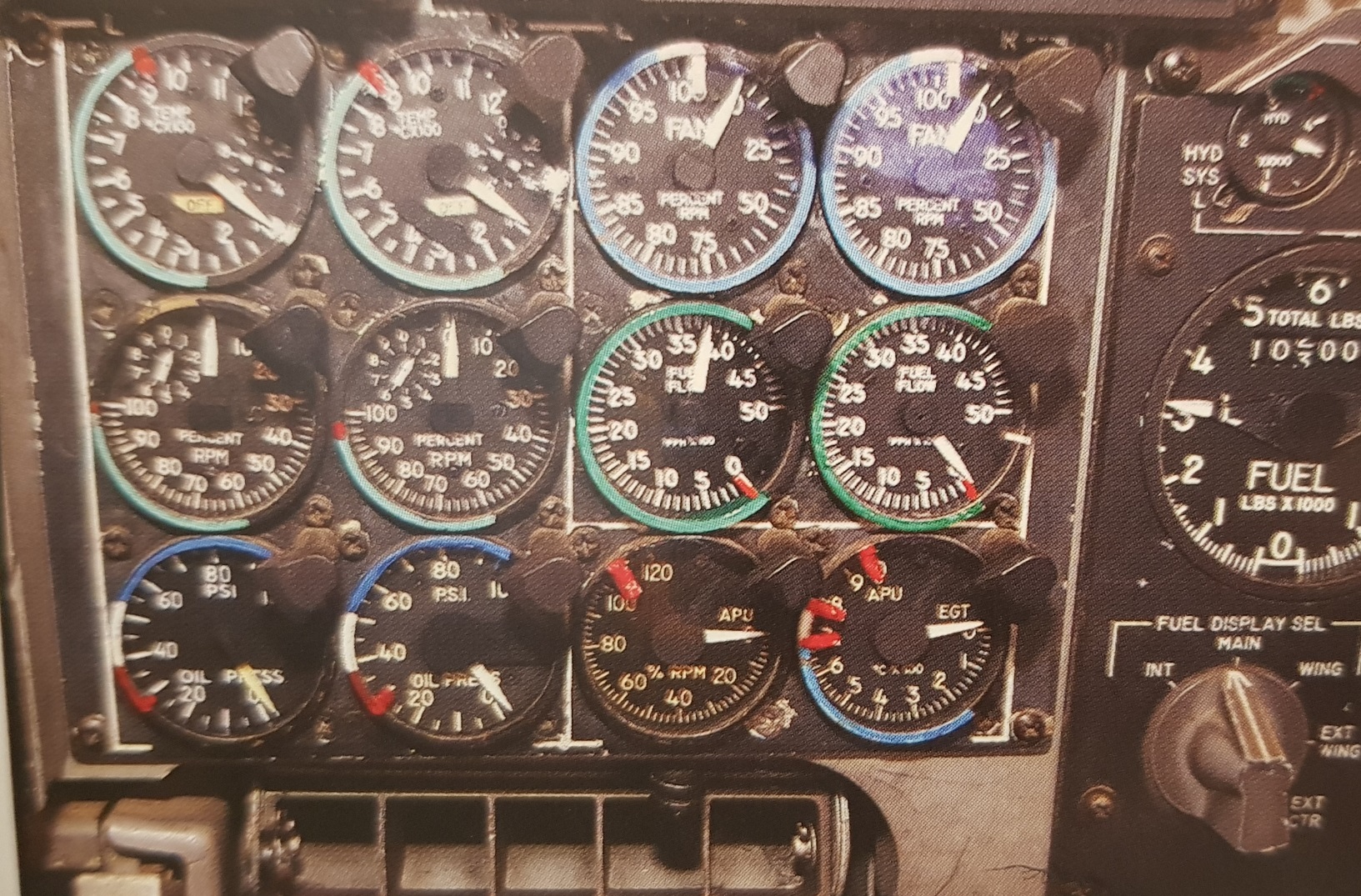
The below picture shows the Engine Instrument Panel in the real A10C
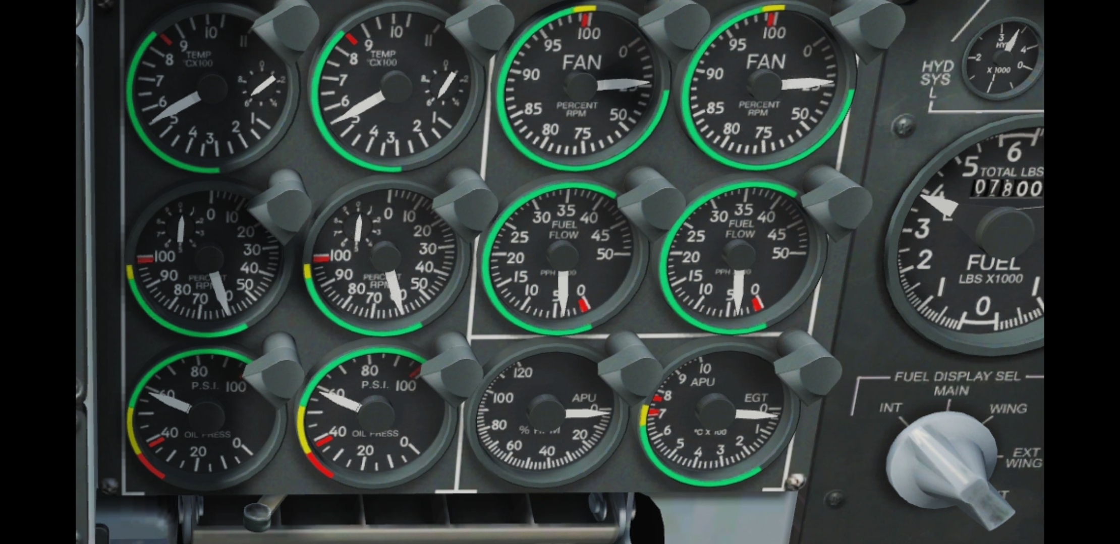
The below picture shows the Engine Instrument panel in Digital Combat Simulator (A10C module)
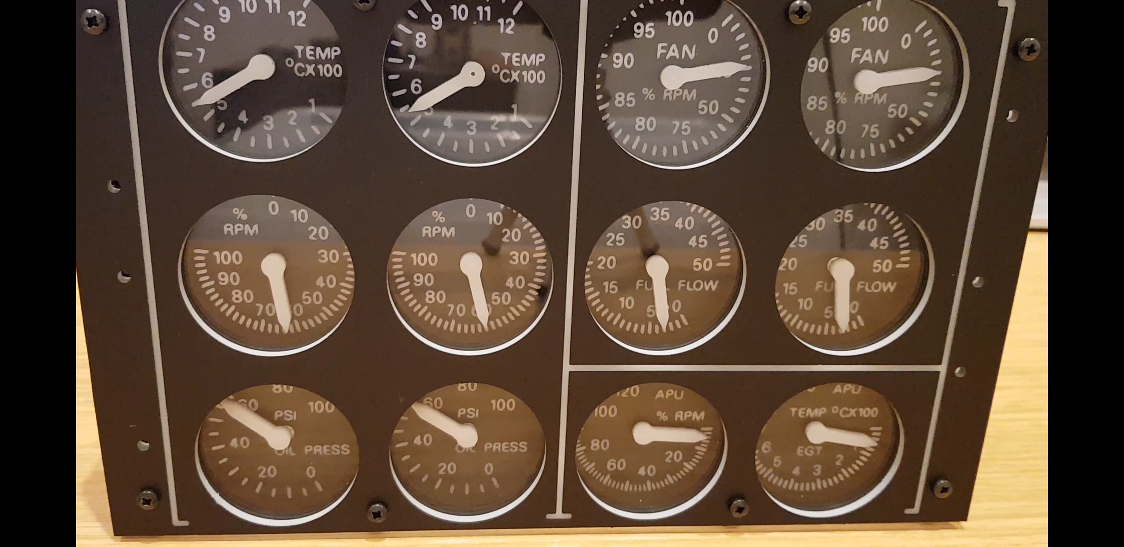
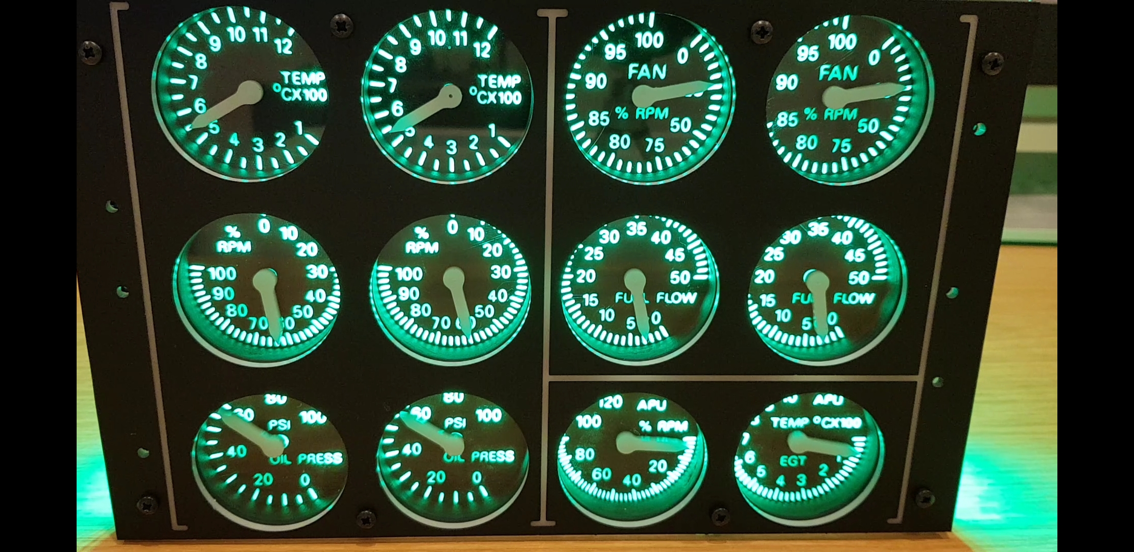
The engine instrument panel consists of 16 gauges and in my simplified version 12 are present. The sub gauges within the Temperature and RPM gauges for both left and right engines are omitted, along with the Temperature gauge flags. I felt that the extent of extra work to implement these relative to what they added did not warrant their inclusion at this time.
During CAD/CAM design I reduced the number of degrees some gauges spanned across their marker lines where this would clearly require a greater range of motion than what the stepper motors can do.
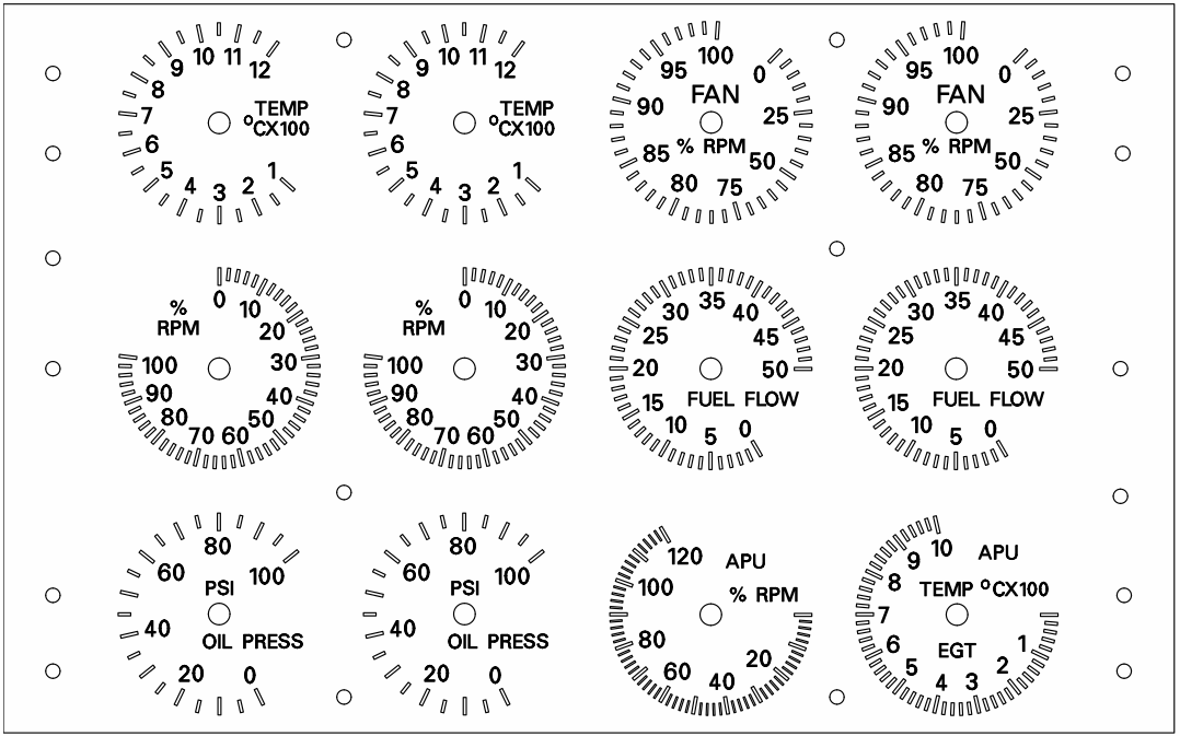
Like my other panels, this was made using 3mm opal acrylic so can be backlit
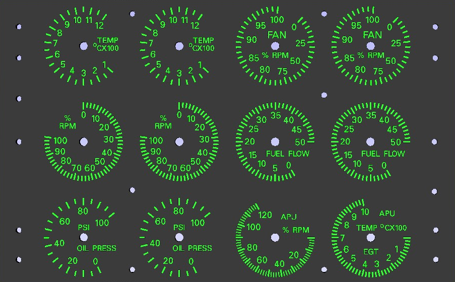
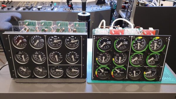
The below two pictures show the completed panel in day and night operation.
I initially built and interfaced this panel into the simulator using DCS bios with all gauges connected via USB. This ran over IRQ serial and needed an open data stream for each gauge, therefore leading to open data streams across 12 com ports. I wanted a solution that involved using less and therefore it was a good time to look into building an RS485 network and convert this panel to run over that network.
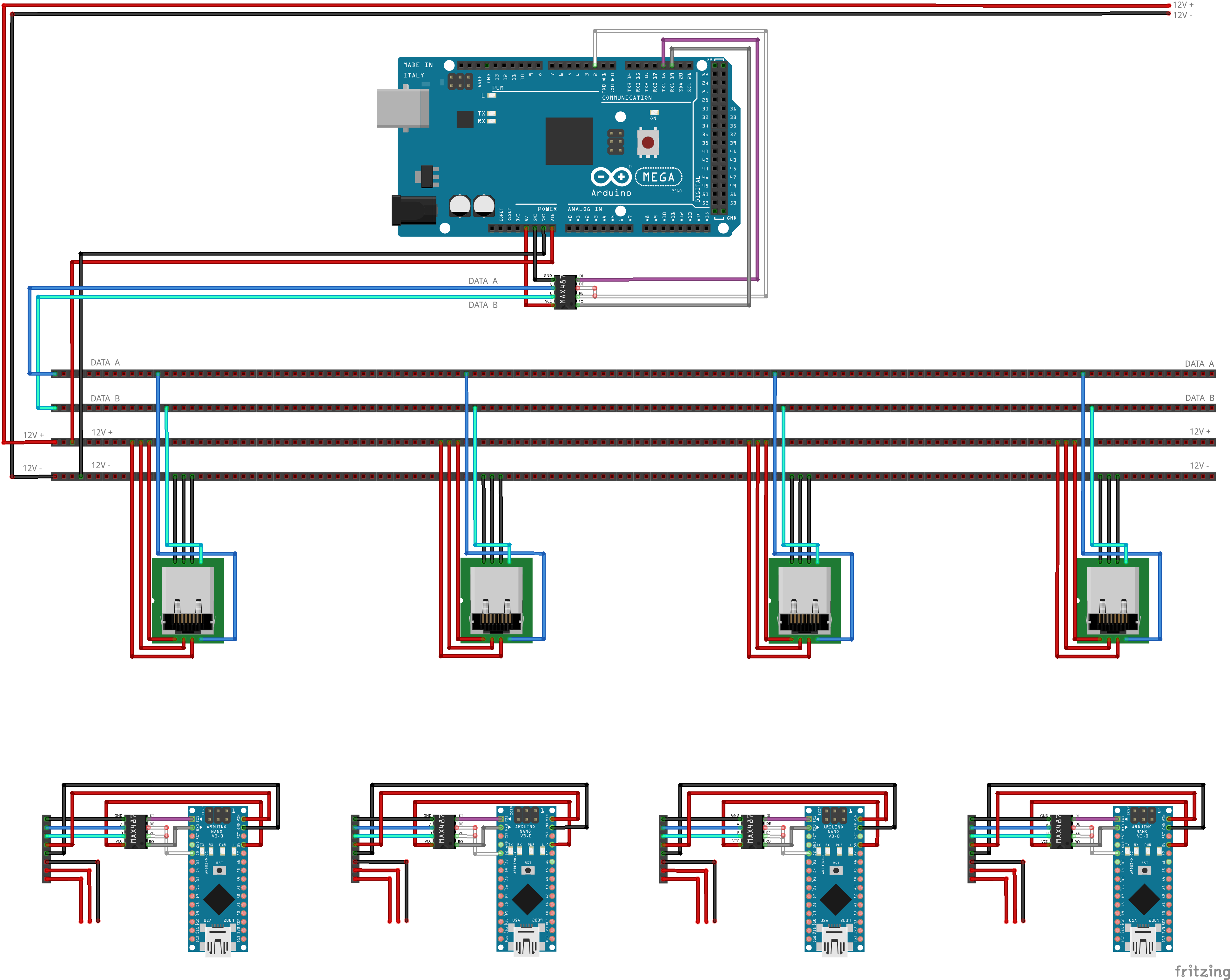
Initial testing and experiments confirmed that certain fundamentals had to be in place within this network for it to function correctly. As per the below breadboard diagram

With the minimum requirements (above) of the network in mind I developed it into the below breadboard view. The plan being to build this network and convert the Engine Instrument panel to run through it.
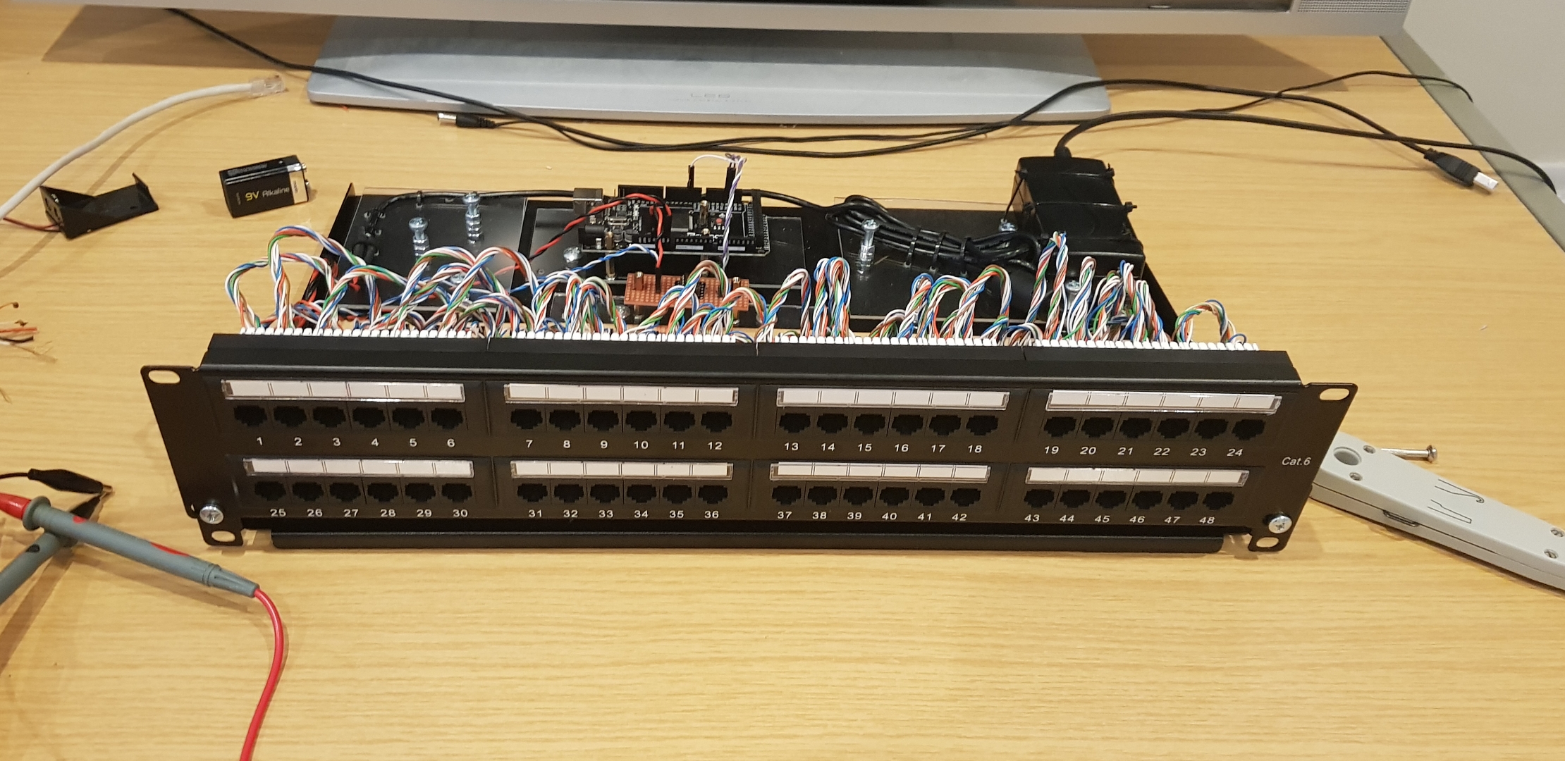
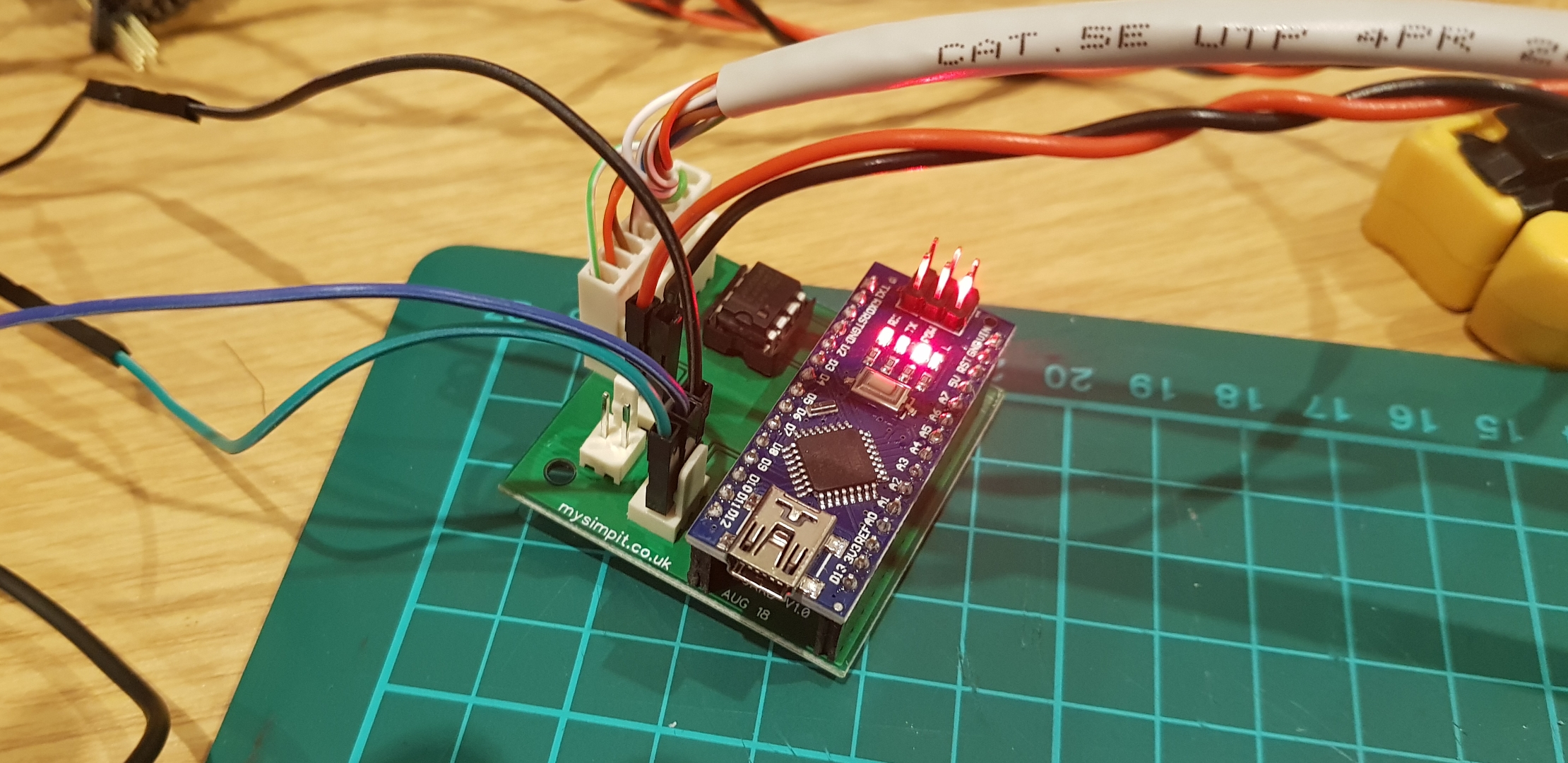
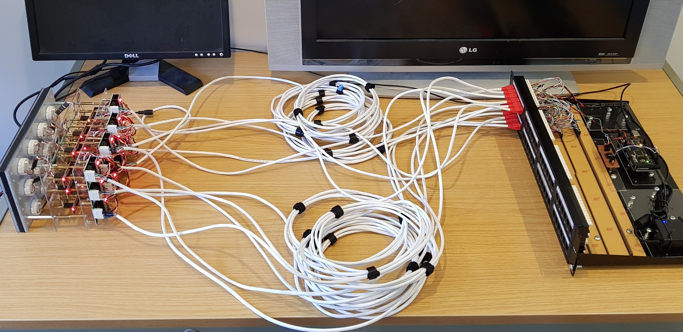
The hub (see picture below) containing the master arduino was built onto a cantilever shelf and all wiring fed into a patch panel. This enabled it to be installed into my data cabinet which acts as the overall central hub for the simpit
I developed my first PCB for the slave Arduinos to plug into.
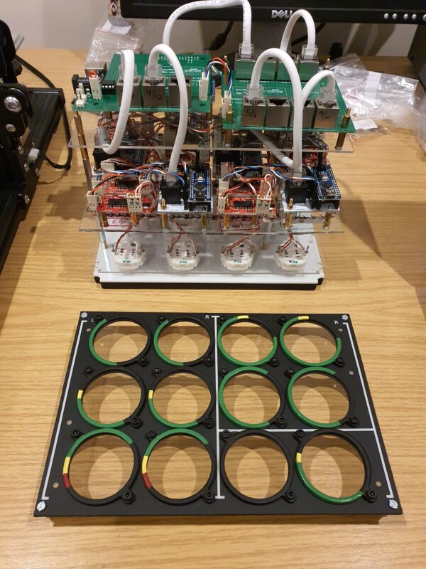
Whilst using MAX487 chips this network, when interfaced into the Engine Instrument panel (see picture below) worked perfectly in tests. A point to note is that the network detailed was built for driving stepper motors and as yet has not been tested in relation to other components. Some element of further adaption may be required for its application in a more generic sense across a greater range of components.
The below video explores the panels construction and conversion to a RS485 network in more detail
To download the Arduino sketch (code) used please see below:
APU Exhaust Gas Temperature Gauge (dcs bios – standard IRQ serial connection)
APU Exhaust Gas Temperature Gauge (dcs bios – RS485 network connection)
Note: If using an RS485 network, the code for the master Arduino is obtainable by installing dcs bios as a library within the Arduino IDE. Then under example sketches for dcs bios the Master sketch is selectable.
UPDATE: March 2020
The prototype detailed above was a great learning exercise. However, I decided to re-do this panel over again for the final version (which was installed into the Front Dash Frame)
The new version has the following improvements:
- Coloured bezzels surrounding each gauge
- Pointer needles attached without glue (to facilitate future maintenance)
- A dedicated station to monitor and interface with the panel. The monitor shows voltage, current draw and wattage along with other information. Three (on)-off-(on) toggles are used to give the ability to reset and test gauges grouped in small clusters of two. I refer to this as the External Monitoring Instruments for the Engine Monitoring Instruments (EMI EMI).
See below pictures for the final version of the Engine Monitoring Instruments (EMI) panel and also a link to two YouTube videos which detail its build and Operation tests.
The new Engine Monitoring Instruments Panel was installed into the front dash with the below panel to monitor aspects of its power usage / consumption.
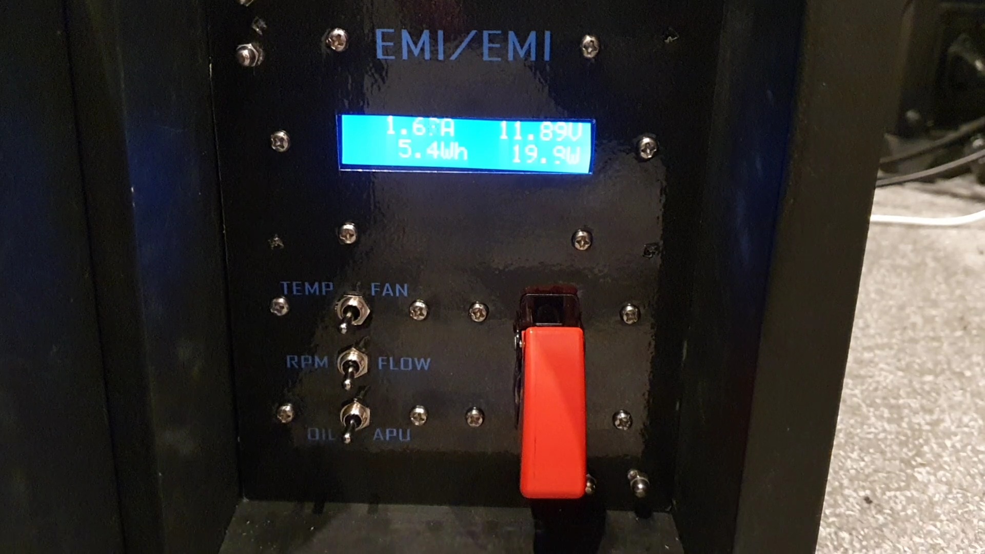
“EMI EMI” – External Monitoring Instruments for the Engine Monitoring Instruments
I detailed this panel through two YouTube videos (links below)
Front Dash Part 19: Engine Monitoring Instruments – Panel Build
Front Dash Part 20: Engine Monitoring Instruments – Operation Test