
The circuit breaker panel is, typically and routinely, a less used panel when flying the A10C.
I still wanted to replicate this panel and it sits currently, in the front Dash frame, as a place holder (as per below photo – situated under the TISL Panel).
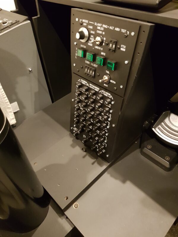
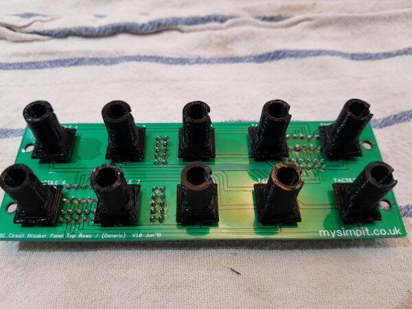
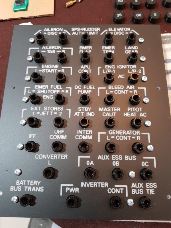
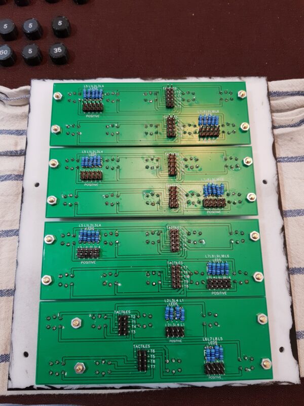
Whilst currently mounted as a place holder, it does have all of the circuitry in place (at its rear) to wire and interface into the simpit.
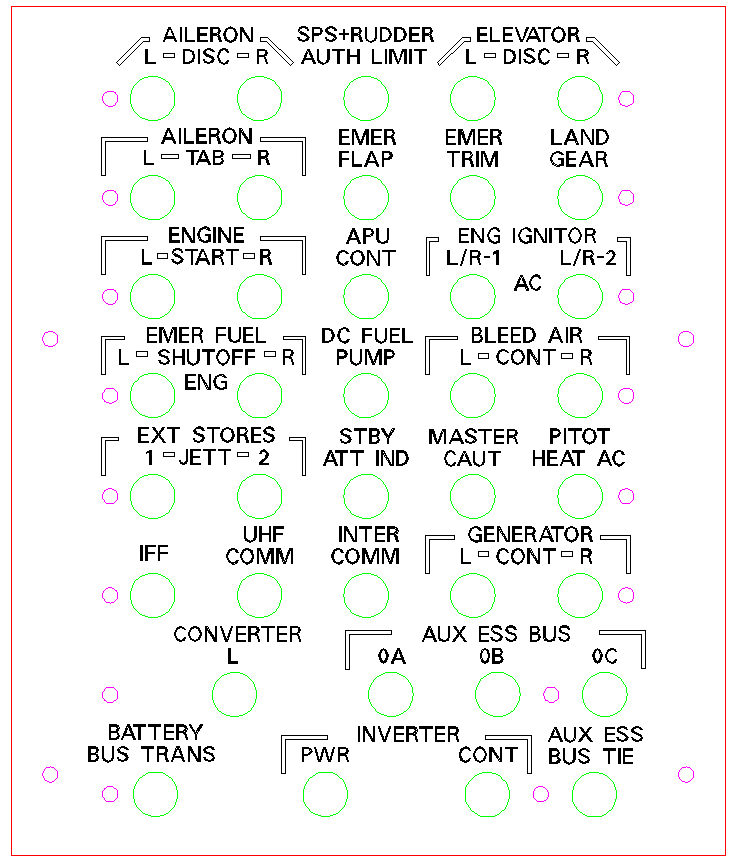
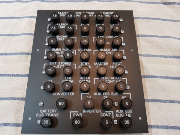
Once interfaced the functionality will enable each circuit breaker to be triggered and reset. Also when a circuit breaker is popped it will illuminate red. I chose a colour distinction from the usual green backlighting to draw attention to this area.
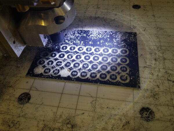
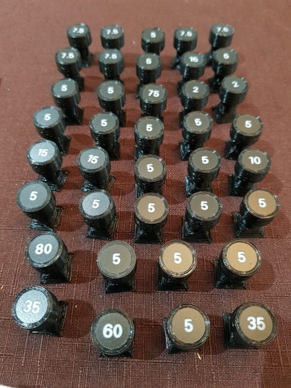
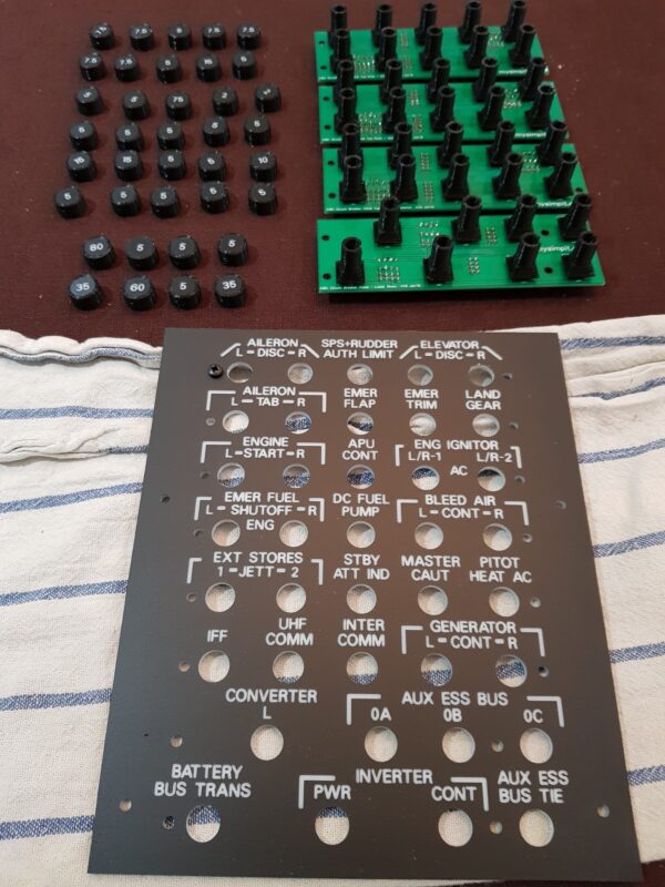
Below are some pictures of the process from design to build.
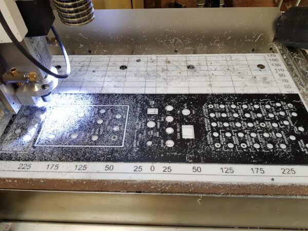
In Part 13 of the Front Dash build (YouTube link below) – the design and installation of the circuit breaker panel is shown at 12 min 25 seconds