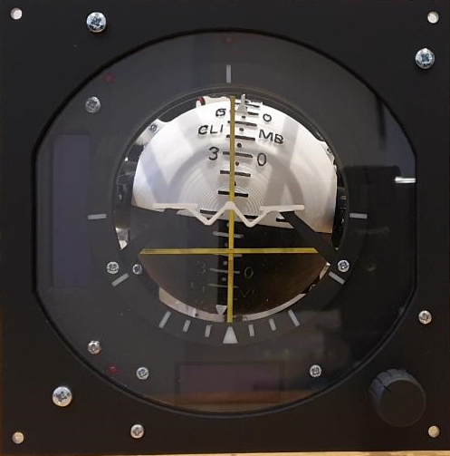
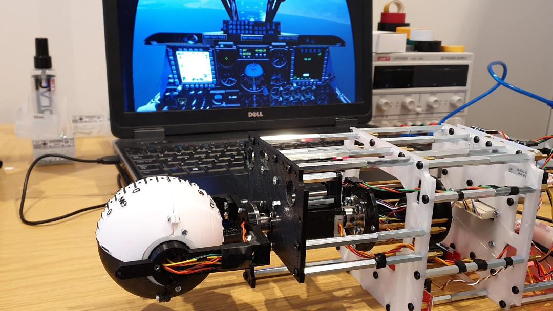
The Attitude Director Indicator (ADI) is one of the more involved panels to build. Certain aspects, such as the warning flags and trim knob are straight forward to implement. However, this panel took me on a journey to explore 3 key design areas.
- How to replicate mechanically the main sphere with pitch, roll and internal lighting
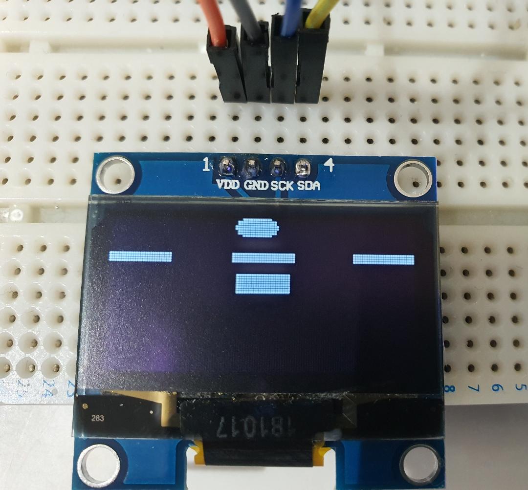
- How to replicate the Slip Ball Position, Turn Needle and Glide slope Indicator via an OLED
- How to replicate mechanically the Steering Bars
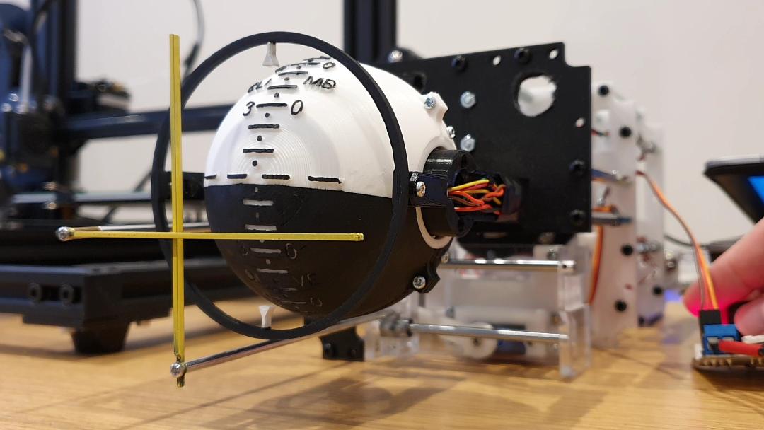
MAIN SPHERE
After a number of tests and revisions I was able to move the pitch axis of the sphere using a servo. This axis only needs to move 180 degrees so the servo is ideal in that respect. However, the resolution of the servo motor did not ultimately give the smoothness of motion I wanted, so I opted for a Nema 8 Stepper Motor instead.
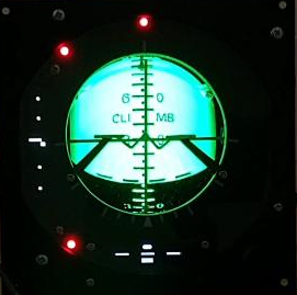
OLED DISPLAYS
I found an article on the website www.flyandwire.com published by Karon. This detailed a project outputting data from DCS KA50 and display it as a moving graphic on a TFT screen. I reach out to Karon and during a collaboration we produced a sketch which would enable the A10C ADI Slip Ball and Turn Needle to be drawn on an OLED screen as a moving graphic. Many thanks for your time Karon – appreciated.
See the below link – to the original article
DCS-BIOS and Arduino TFT – Fly-And-Wire (flyandwire.com)
See the below links for the ADI Slip Ball / Turn Needle (Collaboration) Arduino Sketches.
The first sketch is for use with a 1.3″ SH1106 OLED and this runs smoothest. The second sketch is for use with OLEDs which use SSD1306 library. So typically 128X64 and 128×32. NOTE: If using a SSD1306 display, don’t forget to amend the Adafruit_SSD1306.h file to define the display resolution.
STEERING BARS
The best method I have found to create linear motion from a servo motor has been rack and pinion. However, the rack does extend outside of its footprint which is problematic for ADI steering bars where dimensions for it to be housed are limited.
The solution was a cam design as visualised below (shown in relation to the main sphere)
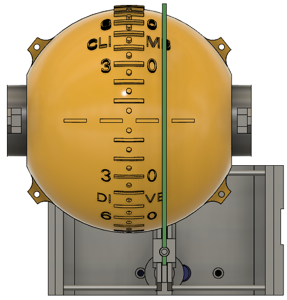
The final version of this is shown in the below gif. I would like to give a shout out to my father in law, Phil, who helped massively in creating the revision necessary for it to function effectively. This took a fair amount of time to reach the refinement achieved. Cheers Phil, much appreciated.